Pid Controller Cascade Process Control System
A Tutorial On Cascade Control Control Notes

Cascade Control An Overview Sciencedirect Topics
An Implementation Recipe For Cascade Control Control Guru

Feedback Control Cascade Control And Ratio Control Free Tutorials Process Control The Process Control Information Page Of Knowledge Based Engineering Pty Ltd Australia
The Cascade Control Architecture Control Guru

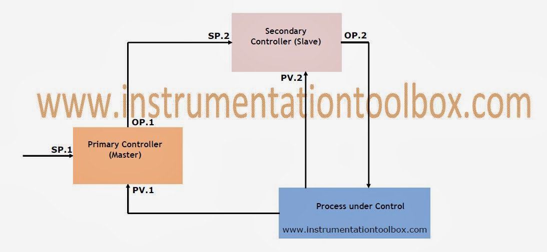
Cascade Control System Diagram As Shown In Fig 1 The Block Diagram Of Download Scientific Diagram
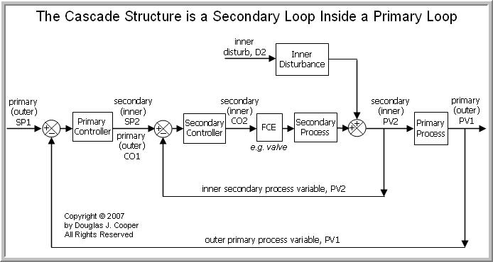
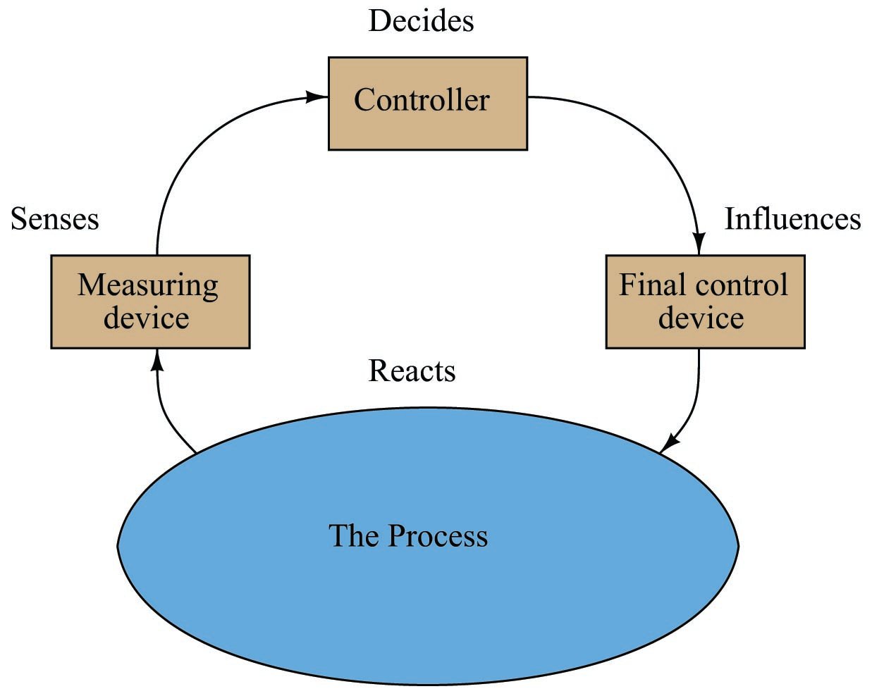
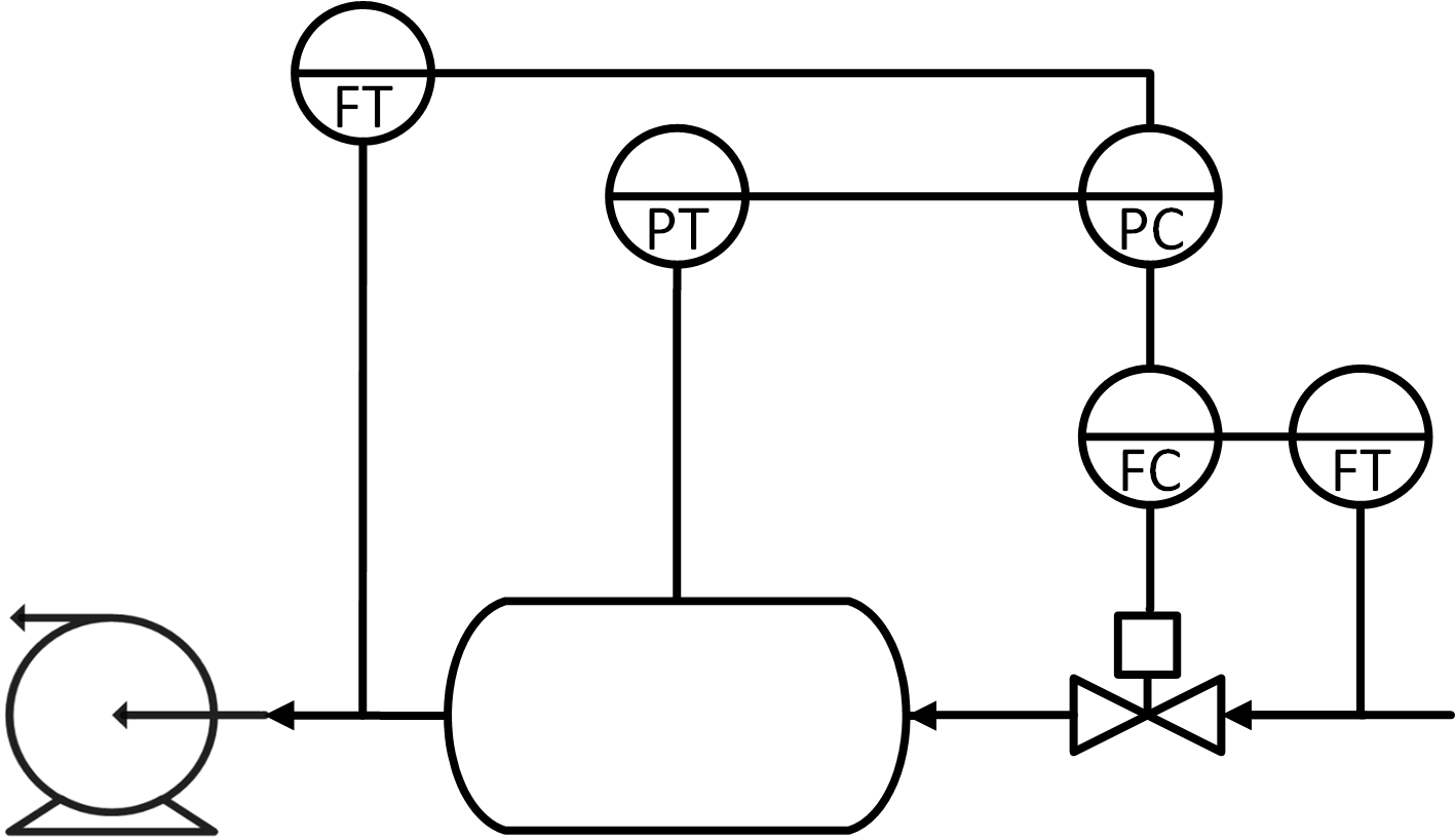
The cascade control block diagram shows a generic cascade control system with two controllers two sensors and one actuator acting on two processes in series.
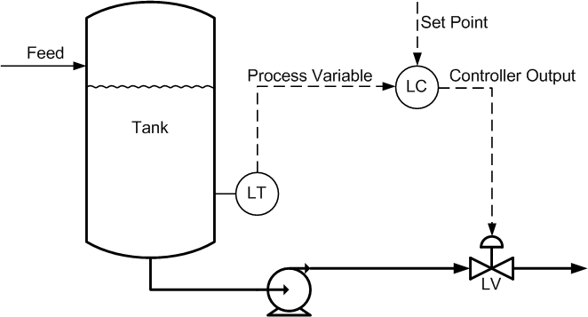
Pid controller cascade process control system.

Cascade Control Design Introduction Youtube

Cascade Control Costs And Other Considerations
Cascade Control Basic Process Control Strategies And Control System Configurations Automation Textbook
Closed Loop Control System With Cascade Pid Controller Download Scientific Diagram

What Is Cascade Control How Is Cascade Control Configured

Structure Of Cascade Pid Controller Download Scientific Diagram
Process Control Basics Cascade Control Learning Instrumentation And Control Engineering

Comparison Among Some Well Known Control Schemes With Different Tuning Methods Sciencedirect
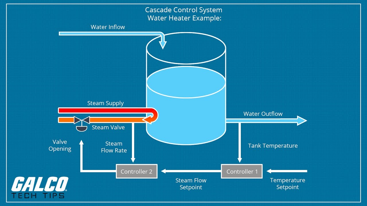
What Is Cascade Control A Galco Tv Tech Tip Youtube
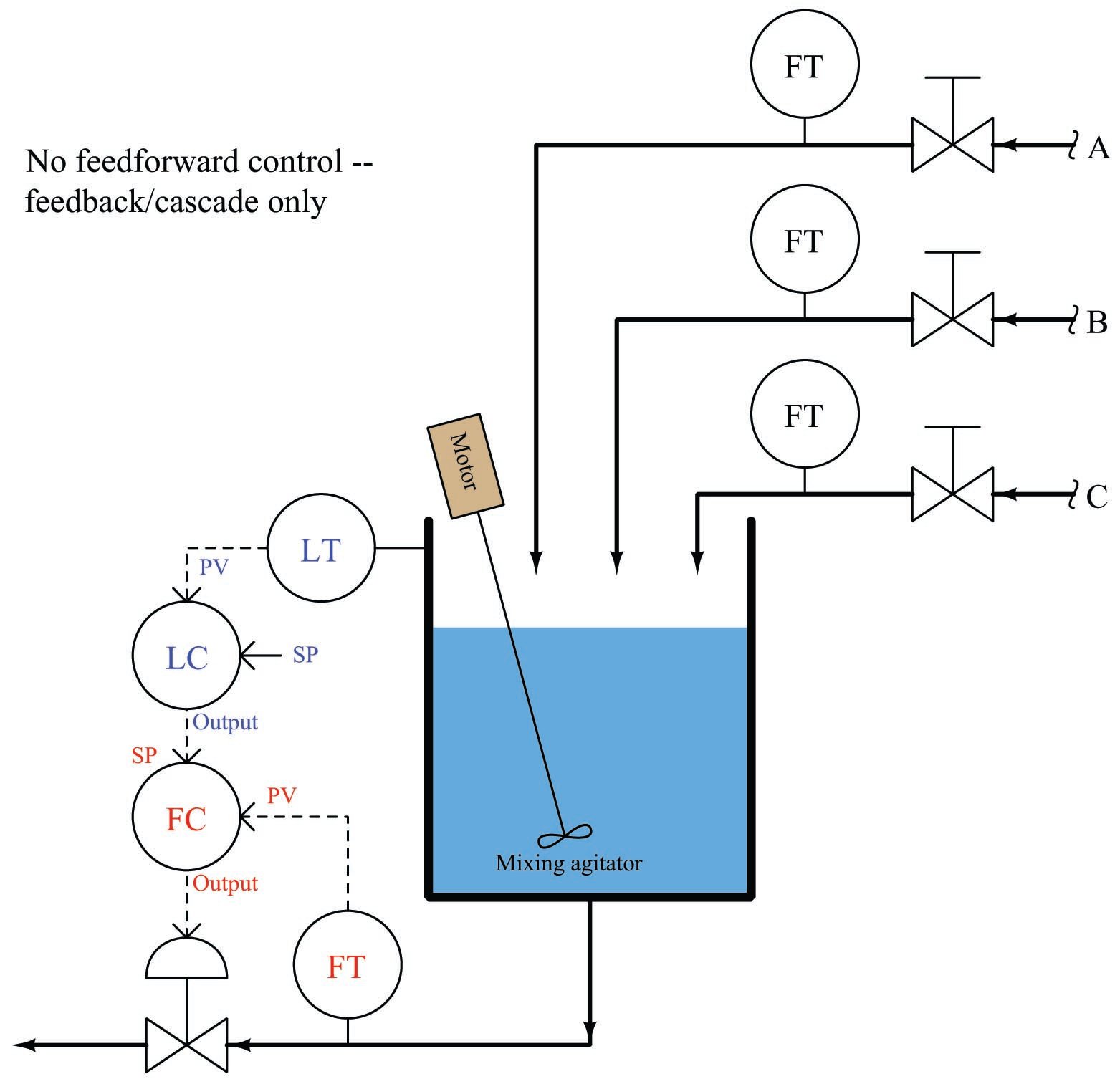
Feedforward Control Basic Process Control Strategies And Control System Configurations Automation Textbook

Introduction To Pid Control Machine Design
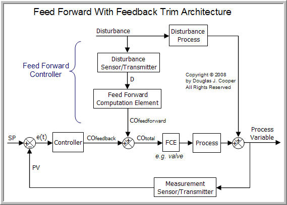
The Feed Forward Controller Control Guru
Control Engineering Tuning Pid Loops For Level Control
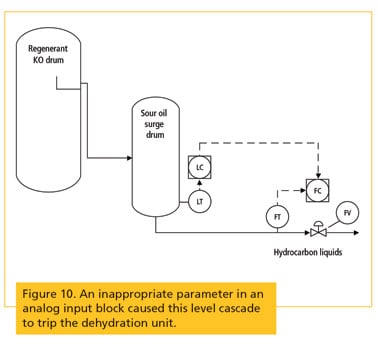
How To Fix Process Control Loop Problems That Pid Tuning Cannot Correct
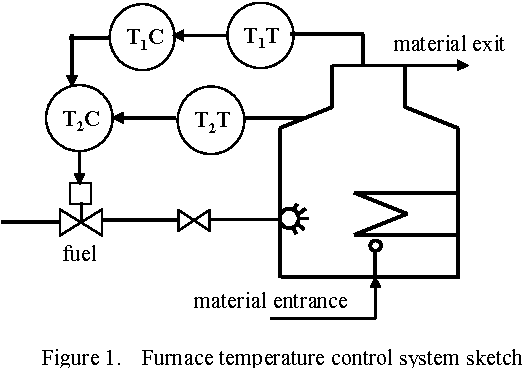
Figure 1 From Simulation Of Furnace Cascade Pid Control System Based On Matlab Simulink Semantic Scholar
Process Control Introduction Dynamics And Control

Figure 10 From Pid Controller Tuning Of Cascade Control Systems Using Genetic Algorithm Semantic Scholar
Http Www Ijemr Net Doc Areviewoftuningmethodforcascadecontrol 61 69 Pdf
1

Experimental Validation Of Pid Based Cascade Control System Through Scada Plc Opc And Internet Architectures Sciencedirect
Controller

Pdf Pid Controller Tuning Of Cascade Control Systems Using Genetic Algorithm Semantic Scholar

Pid Control System Design And Automatic Tuning Using Matlab Simulink Design And Implementation Using Matlab Simulink Wiley Ieee 1 Wang Liuping Amazon Com

Design Of Pid Controller For Cascade Control Process Using Genetic Algorithm Semantic Scholar
Source : pinterest.com
